how to draw a 3d picture easy
How to depict any building in Isometric view
94,780 views
Introduction
Hello everyone, I'm Steele.
When nosotros think about how to draw an object in 3D, Nosotros gonna think nigh perspective drawing correct?
Only there is some other method out at that place that chosen ''Isometric drawing'' which is an excellent method to draw something in 3D, and later on nosotros are gonna talk virtually what is Isometric drawing and what benefit almost this method.
and in this tutorial, I'one thousand gonna share you guys several tips in how to use some ruler and other features in Prune Studio Pigment that can benefit your workflow fifty-fifty more!
What is Isometric drawing?
The term "isometric" comes from the Greek ίσο μέτρο "íso métro" pregnant "equal mensurate", reflecting that the calibration along each axis of the project is the same.
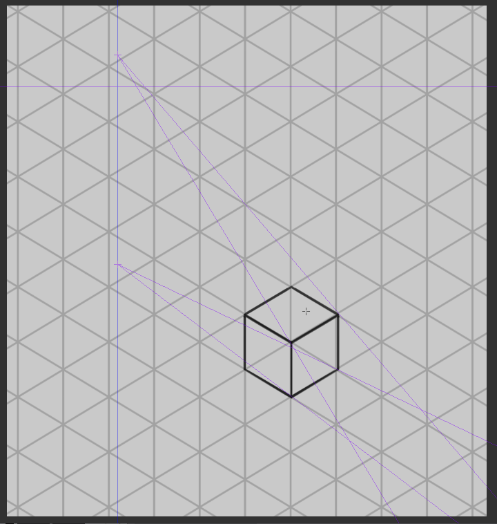
An Isometric drawing is a 3D representation of an object such equally building, room or design that oft used by artists and designers to represent 3D forms on a 2d moving-picture show plane. In this method, the object appears as if it is existence viewed from the elevation, with the axes beingness set out from this corner point. Isometric drawings begin with one vertical line along which 2 points are defined. An angle of xxx degrees is taken in all its sides in club to requite a 3D look.
Considering all edges of an isometric object are inclined at the same angle, they are equally foreshortened. That allows you lot to take measurements of each side of an object using the same scale.
People tend to confuse past the drawing between Isometric cartoon and Perspective cartoon. Isometric and Perspective both are unlike things.
Both isometric drawings and 1-betoken perspective drawings use geometry and mathematics to present 3D representations on 2D surfaces. and now I gonna tell you almost what is the divergence betwixt these ii.
Normally our eyes see objects in perspective. There are iii types of perspective projections: ane, 2 and 3-indicate perspective.
1-bespeak perspective drawings mimic what the human being eye perceives, so objects appear smaller the further abroad they are from the viewer. This effect is ordinarily achieved by using Vanish Points. You depict your first vertical line where ever you want, and and so just extend the diagonal lines to the vanishing points. The rectangular prism beneath is in this perspective/project. It is a parallelogram but appears to slowly get smaller.
An Isometric view is a view in which the image has no vanishing point. This is in dissimilarity to a perspective epitome drawing, which tin have multiple vanishing points. A vanishing point is where parallel lines converge. No thing how far the object is the scale will remain the same. This makes an Isometric drawing be more useful for portraying accuracy merely doesn't brand for a very creative image or how we humans perceive the world around us normally.
The reward of cartoon in this manner is that an object tin be freely rotated, re-positioned and reoriented without redrawing it. At that place is also no change in the sense of scale when an object is moved forrad or astern. With other drawing techniques such as perspective. it is non possible to reused already drawn items. They will need to exist re-drawn from scratch.
An Isometric drawing doesn't use perspective in its rendering. Isometric drawings are more useful for functional drawings that are used to explicate how something works, while perspective drawings are typically used to give a more than sensory idea of an object or space.
Isometric drawings are very useful for artists and designers - particularly architects, industrial and interior designers and engineers, as they are ideal for visualising rooms, products, and infrastructure. They're a nifty fashion to quickly test out different design ideas.
an Isometric view allows artists to create a 3D object without calculating circuitous calculations, foreshortening, and unlike camera view angles. Maybe this is why Isometric drawing is also used widely in video games and in modern illustration.
Tools Grooming
Before we become to the main topics. nosotros need to have tools that can let you draw in Isometric view more easily. so nosotros gonna prepare important tools that we gonna utilise in our Isometric cartoon offset.
The main tools that we gonna use in the Isometric cartoon have 2 of them which is Isometric snap-ruler and Isometric filigree.
with these tools and other Clip Studio Pigment features, this gonna assist our work in Isometric drawing much easier.
and I gonna share y'all guys how to make an isometric snap-ruler with a perspective ruler and tips that how I use an isometric grid in my workflow.
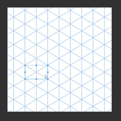
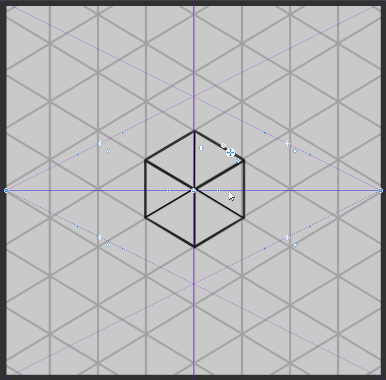
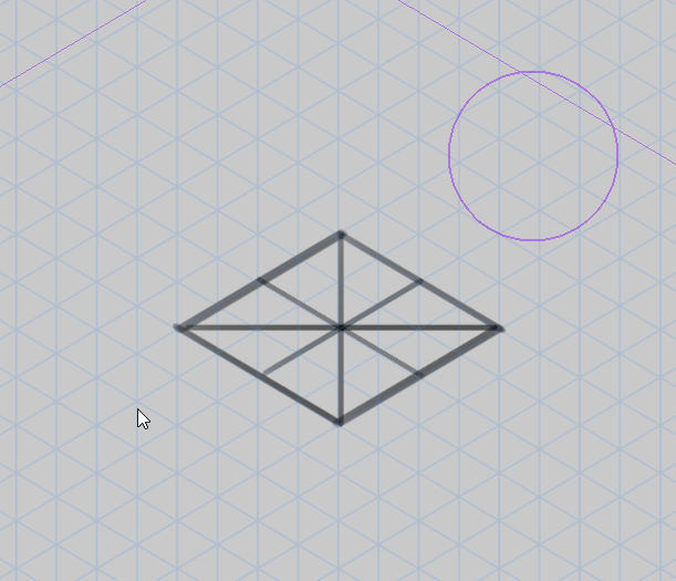
one. Offset, I've created a foursquare with [Effigy] > [Straight Depict] > [Rectangle] hold the shift key to brand their scale equal to each other.
two. Then press [Ctrl+T] to [Complimentary transform] the object that I've made.
three. Agree the shift fundamental and click outside the square if yous can notice that the cursor had inverse, then I keep to rotate the object until one side of corner facing the ground. and press [Enter] key or Click [OK] to confirm the change
iv. After that, I press [Ctrl+T] to [Free transfrom] the object once again. Then go to [Tool property] menu, uncheck Continue aspect ratio and change Scale ratio of Superlative 100 to 60 and press [OK] to confirm.
you tin meet all angles of the object will be 30-degrees, which is the angles that used in Isometric drawing.
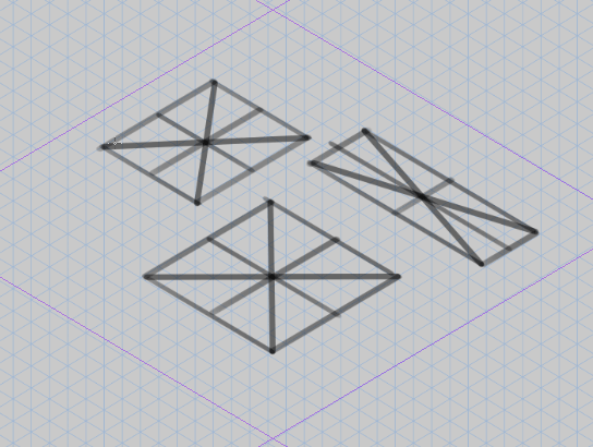
5. I will utilize [Figure] > [Create Ruler] > [Perspective Ruler] with a default setting, create 2 lines according to the object that I've created between the two sides like the picture below.
in order to make those lines perfect parallel to each other, Just in case I utilise [Perspective ruler] then change to Process to Infinitize. After that, click on ane line of those two to make them perfect parallel to each other.
6. I've repeated the same stride with the other side.
vii. Next, I've created a ruler for a vertical line. Hold shift to make those line vertical and place them where ever yous want them to be.
Now the Isometric snap-ruler is now completed!
Before we gonna get to test the ruler that I've created, brand sure you already snap the ruler. In order to make the ruler take upshot on the line, you need to active those Snap Ruler first.
The fastest way is to look at the top of the control bar on the right.
i. On the left is [Snap to Ruler] The shortcut fundamental is [Ctrl+1] this snap with work with [Linear ruler], [Curve ruler], [Figure ruler] and [Ruler pen].
2. In the middle [Snap to Special Ruler] The shortcut key is [Ctrl+2] this snap with piece of work with [Special ruler], [Perspective ruler], and [Symmetrical ruler].
iii. On the right is [Snap to Grid] The shortcut key is [Ctrl+3] for the Grid that we create
Throughout my workflow, I disable and enable the snap a lot that sometimes tin can slow down my workflow. So instead of click at them on the control bar, I tend to utilize a shortcut cardinal instead, Information technology makes a lot easier for me to switch between free drawing and snap drawing.
After active the Snap, I've tested the lines on the ruler to meet is information technology working properly or non.
You lot can as well change the color of your ruler depends on your preference such as ruler, grid etc. In the Preferences setting.
For who thinks making Isometric ruler is too difficult to brand, Don't worry I already make one for you lot!
you lot tin can download an Isometric ruler and Isometric grid in Clip Studio Assets that I've made from the link down below.
Inside of this Textile catalog also have Isometric grid likewise. so you guys gonna remember why we still demand Isometric grid when nosotros already Isometric snap-ruler correct? Merely when I disable the snap ruler I need to draw freehand without anything to guide my line. And then you can say this Isometric grid will come up in handy when I need to work in freehand like sketching.
So I gonna share you guys how I use this Isometric filigree in my workflow.
Later on you drag an Isometric filigree from the Material Folder to the canvass. The layer of an Isometric ruler will appear.
you can reduce the opacity of the layer to get in less outstanding, I often reduce the opacity around twenty%-40% depending on what I'm working on that process.
and I don't similar my Isometric grid to be black color because I'1000 using black color to sketch and line art on my works and I'm non desire to get myself misfile by the aforementioned color betwixt line art and the gird.
In order to change the color of the layer you need to go to [Layer Belongings] > [Event] > [Layer colour] in Clip Studio Paint default setting volition be a blue color. you lot can change the color depends on your preference, click on the pointer next to the blue colour box to modify the color or chose your color and click on the blueish color box.
Sometimes the grid is too big or as well minor. you tin can use [Performance] > [Object] click on the Isometric Grid and rotate or rescale depends on your preference.
That's all for the Tools Preparation. After we larn how to utilise these tools the Isometric drawing will be much easier than earlier.
How to draw an Isometric firm
In this topic, I'one thousand about to draw a simple house in Medieval mode with help of Isometric ruler and filigree that I've created. I also gonna share some tips on how to use Clip Studio Paint that helps my workflow much easier.
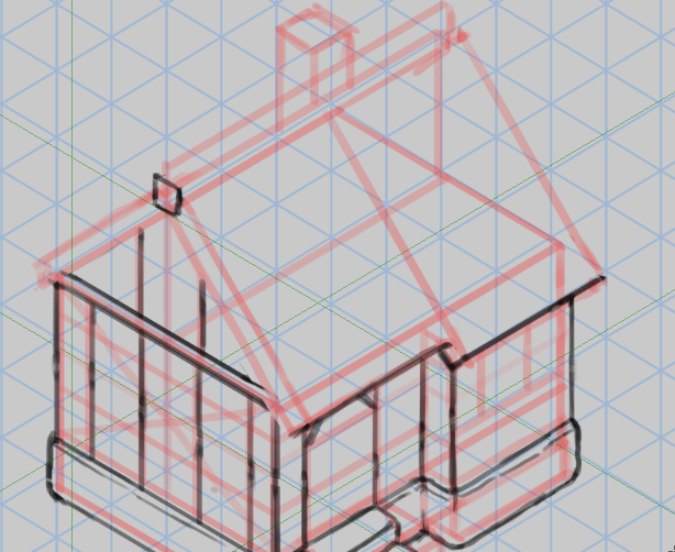
First, I depict a simple structure to see what my building gonna look like in the simplest way as possible. So instead of jump in and drawing my building in isometric view, I just draw the front view and the left view of the building. this technique gives me enough information from the different side of edifice in second (because drawing object in 2nd is much easier than drawing in 3D) earlier nosotros gather them together.
(Think this technique is optional, you can just jump right way and draw or sketch in Isometric view. this technique that I'm about to perform just to permit yous know a different way to create Isometric cartoon.)
Next, I sketch my house very loose to encounter how my building gonna looks like from the different side.
the building is very simple since the principal form of the building is a rectangle. Afterwards the sketches, you can tell how is this building gonna look like because we already give a lot of data to the different sides.
don't permit them stay on the same layer, just go on them on a different layer because when I use [Ctrl+T] to [Gratuitous Transform] the layer so I tin can complimentary transform them 1 past one.
Subsequently making sure everything is fix to go, I set up my Isometric grid in to place. gear up to assemble my house from second to the 3D Isometric view.
and I also set a scale on my house from every side of the building. this let me figure out where to assemble my hose to an Isometric filigree that I simply created.
so my building size is (4+1x5x5) ane box will equal to 1 box in the Isometric grid.
And so, I draw a cerise line according to my edifice size. this lines will help me see how my building gonna looks like in Isometric grid.
Next, I'm preparing my house set to assemble I will be starting with the front view.
i. Click the layer of the firm front view and use the shortcut [Ctrl+Shift+T] to [Free Transform] the object.
2. After that, I click on the box in the corner. And so I drag every corner of the object to a place where I desire to be, Similar the GIF motion picture down below.
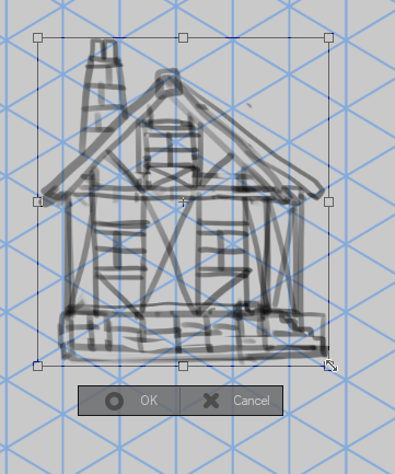
3. elevate every corner of the object to line up with the red line of the building that I created. Similar the moving picture on the top
four. Repeat the same step to the side view.
Washed!
the results come out very bad for me because I don't get to this technique, and then I kinda perform out and then poorly LOL (I'm sorry about that). Just still, I remember this technique is very effective and easy to perform. information technology besides helps you know how to create an isometric drawing in a different way, that plow elementary 2d cartoon to 3D drawing.
So, let'due south caput to the next process.
Side by side, I go on to place an Isometric ruler on my canvas ready to draw in Isometric view.
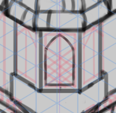
I draw a structure and adding depth on of my house with Geometric shapes such equally cube and pyramid on the top of my Assemble firm, to see how edifice gonna looks similar overall in Isometric view. and I draw the line where are the door and windows will be placed on the building according to our sketch.
In this procedure, the snap-ruler is very useful since most of the drawing is a straight line that parallels with the Isometric ruler.
I remember this is the almost important part of the whole process, where we need to notice the construction of the object that we correspond in 3D or Isometric view. So have your time when yous drawing the structure of your building.
After finished drawing the structure of the house, I start to draw the actual line on my house and hide the assembled business firm since I don't need it anymore but I even so use information technology as a reference of my building. I've added some depth and requite information technology a clear wait at the stair of the building.
When it comes to the rooftop I demand to apply the tool that tin can describe a line that parallels to each other, since the Isometric snap-ruler that I've created can't depict the line that is against the ruler (this is something that Isometric ruler can't practise. so sometimes I need to apply other rulers to fulfil this part)
So, I'1000 gonna create another ruler that tin can do this task for me.
ane. Go to {Figure] > [Create ruler] > [Special ruler] > [Toot Holding] change to special ruler to [Parallel line]
2. Place it and adjust on the angles of the line that you want to describe on. all the line that you draw on when this special ruler is present volition parallel to each other.
You can see the Special ruler working perfectly well. You lot tin can change to angles of the ruler with [Object] tool.
But when special ruler's layer is present somehow it gonna automatic disable my Isometric snap ruler. In order to brand it agile or able to snap once more, you lot can become to [Performance] > [Object] click on the ruler that you desire to be active again. later that, go to [Tool Property] > and brand sure to bank check on the ''Snap ruler''.
And now your ruler is active and prepare to apply once again.
Next, I describe chimney on the top of the roof and adding some guideline on the bottom of the building and the chimney on the roof preparing for a rock panel in the next process.
I go on drawing a stone panel from the guideline that I describe from before with my freehand without Isometric ruler. Try to brand them small and big. since a stone panel beingness mixed past the different size and shape of stones.
later on I've finished drawing that office, I fixed to line around a stone panel to lucifer the stone on the border. Intending to adding depth into my house.
Come to the main building role, I depict a timber frame around the building. and I've added the windows frame and wooden door base on the structure/sketch edifice that I've created. After that, I've added some depth to each timber frames to give information technology a more than 3D await.
About of this part, I've used Isometric to draw these timber frames and windows.
Afterwards added timber frames and windows, I hide the structure layer since at present my house already accept a clear shape. I get-go to adding timber braces that connect each timber frames (ofttimes meet in medieval building styles). with this timber frames and braces gives a medieval look on my building.
In this process, I've used [Linear ruler] to guide my line and apply my free hand to describe these braces.
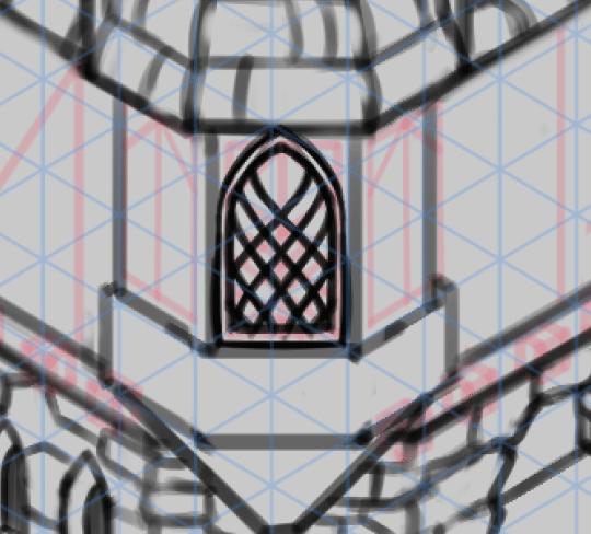
Subsequently I've finished with the main building part, roof tile is the only matter left that I need to describe in the process.
I need to brand sure that my roof tiles parallel to each other, then I draw some guideline with Isometric ruler helps to prepare in the next process.
I've continued to add to detail to the rooftop, drawing them i past one. In this procedure is kinda the aforementioned as the stone panel. Try to draw with my free hand it very ho-hum, using the lines that I've created and Isometric to guide my eyes. I also tend to draw the independent shape of each roof tiles, avoiding the boring wait.
After I've finished everypart of building, I try to fix and add some pocket-sized details into my building.
I've deleted the layer or hide the layer that I don't anymore. and then, I want to fill my building with color that will help me in paint shadow in the next process. so I choose this technique to exist fill my firm.
i. Outset, I select the house layer or my line art layer
two. I set this layer as a [Reference layer] (Later that, yous tin can run into the same logo appear in the forepart of the layer)
3. I select [Automobile slect] > [Refer to editing layer only] > [Tool property] I check '' Multiple referring'' > and choose ''Reference Layer'' (This setting wherever you use this tool, everything volition base on the reference layer)
4. After the setting has set in place, I've created a [New layer] to be my color layer.
v. I've used [Refer to editing layer only] > click on the outside of the edifice and the selection expanse will appear on the canvas
6. Y'all tin can run across the mini-menu that appears on the bottom of the option. I click [Capsize selected area] and you tin can encounter the selected area Invert to the space inside the building.
7. After that, I cull the colour that I want to be my base of operations color. > And so I click [Fill] on the mini menu to fill the area with my called color.
Washed!
This technique is very fast and very effective to fill up the area or an object, which I used a lot in my workflow.
Side by side, I will add together a Shade on the building, and as well I'm gonna share you the tip on how I create a bandage shadow In 3D drawing.
How to draw cast shadow
In this topic, I gonna talk about cadre and cast a shadow and share you guys how I use the Perspective ruler in Clip Studio Pigment to find the cast shadow of my object in 3D view.
which this technique works very well with both Perspective view and Isometric view.
So, I'm gonna talk about what is the difference between cadre shadow and cast shadow.
Cast shadow is the darkness that results because an object blocks light from hitting another object.
Light from other sources will change how the shadow appears.
Often shadow farther from the object will exist less dark and less crisp. In this image, notice that the light reflecting from the pitcher brightens a part of the shadow from the block in front end of it.
The shape of the cast shadow is important, as it can give your viewer clues every bit to the shape of the object.
Core shadow is the dark part of an object that doesn't receive light. The front of a bullpen, for case, reflects light toward the viewer and the backside is in shade. The pitcher casts a shadow on the footing and wall. Core shadows tin can tell the viewer about the grade of the object in the scene, while bandage shadows imply the shape of the object and the direction of the light.
This method was used past a 2-bespeak perspective. Then, we'll talk most this method in a 2nd view for better agreement on how is this method works.
1. [Light source] is the offset vanishing signal in this perspective. every lite line will produce by this vanishing point
2. [Light direction / Shadow vanishing signal] is the 2d vanishing bespeak in this perspective. this calorie-free will tell us where is the light direction is, and how the shadow gonna looks like.
3. [Light angle] is the light or the line produced by the light source. the light angle will outward and over the top corners of the form to the ground. And where the line of the light angles and the low-cal management lines intersection it will create mark an bodily form of cast shadow that bandage on the basis.
After nosotros learned how this method works, I will try information technology in an bodily 3D Isometric view.
First, I go to [Layer] > [Ruler - Frame] > [Create Perspective Ruler]
Later click on it, a mini menu will appear. Then, Choose [2-points perspective] > and click ''OK''.
It will create a new layer and 2-point perspective will show upwards on the canvas.
Get-go, we need to know how perspective work beside create a line that following the vanishing point. I will use [Operation] > [Object] tool to show you how to change this 2-indicate perspective ruler to a 2-point perspective that nosotros gonna use to predict the cast shadow.
I volition explicate what these dots do to the Perspective ruler and how to utilise them to custom the ruler.
1. motion the position of the vanishing point according to the horizon line.
2. movement the guideline of the vanishing bespeak.
3. move the horizon line of the ruler.
4. rotate the horizon line of the ruler.
5. rotate the guideline of the vanishing betoken.
A better way to understand how this ruler works, Information technology's just trying to play with them and test in a diverse style.
I've created a square on the canvas and gear up my Isometric grid in identify.
I go on to custom the ruler, I press [Shift] and rotate the horizon line to a vertical line.
and motility it to the left side of my object.
Afterwards I set up vanishing point and my Perspective ruler in place. I've added the color to the line to you know where are the low-cal source and light direction will come from, fix to perform the next process.
Next, I go on to add the light angle line that produces by the light source outward and over the superlative of every corner of the object.
Y'all can as well add the guideline to the ruler though, instead of draw the line one by one.
You can go to [Perspective ruler] > change the procedure to [Add guide].
Place them on every corner of the object and adapt them depending on your reference.
this tool is indeed very useful since we don't need to draw a line from scratch, y'all tin can just place guideline on the corner and it will automatic following the vanishing point of the ruler.
Only since I want to share the method to anybody who works in a paper and other software
that don't have the features like Clip Studio Paint. I volition go on to do similar the original of this method.
I continue to draw Light direction lines toward the object over every corner.
Later I already take both Lite angle lines and Light direction lines, I take to detect where is the intersection betoken it. then continue to marking every intersection point on the basis to predict the shape of the cast shadow.
Next, when I'm already located where the cast shadow gonna exist I've filled those areas with dark grey color on the ground. and I've added core shadow to my square.
Done! Everything looks so like shooting fish in a barrel, right? Yep is it, Because the object of the cast shadow is then elementary is will be not too difficult to predict since the object is a uncomplicated square. Simply in a circuitous object is a different story for me, the more than complex the object the more the shadow will be. then be careful when y'all utilise this technique.
After, I already have a cast shadow of the first object. you tin try to test on how other objects interact with the same light source and how it cast shadow gonna looks like.
I think is information technology the fourth dimension to use this in my actual work. And so, I've created a 2-bespeak perspective and rotate the horizon line and identify is exterior of my canvass on the right. and After that, I've adjusted 2 of my vanishing signal of my ruler that will Light source and Light direction in the next procedure.
Make sure your ruler is set in identify. then I'll continue to draw my structure edifice again since my onetime structure sketch is likewise messy.
In this procedure, I volition use [Straight line] to draw my structure.
I'm property [Shift] key and draw the house in simple shapes similar the kickoff sketch. I need the unproblematic shape to see the actual construction of edifice because I'm gonna depict the line on every corner of the building to find a cast shadow. you should continue that in mind that, when it comes to this part if something goes incorrect with this process, so you side by side and next process with incorrect too.
when I already have the structure of my building., I depict the Light angles line that comes from Light source. I depict the line to every corner that I think those line with help me find a cast shadow on the basis.
After that, I draw the Light direction line trying to find the intersection point.
you can encounter a lot of those line on my building right now. even in this simple shapes firm will yet make me confuse. Endeavour to make it very slow, correct the line that place in the wrong corner or not.
Next, I have both Lite bending lines and Light management lines. I begin to find the intersection points on the ground. and afterwards I observe where are those intersection points is, I outset to connect the intersection points together creating a bandage shadow shape on the footing.
But be careful though If your structure is wrong your line will be wrong like your structure too. When yous something goes wrong in your workflow, endeavour to await through what causes the problem and fix that Immediately.
I've filled that surface area with dark gray color, and hibernate structure layer and perspective ruler that I don't demand it anymore. and I've adjusted some shapes on the cast shadow in society to make them match the look of the actual building.
So, I create a new layer on the top of my base color. and set layer setting to [Clip to layer below]. I'one thousand virtually to add core shadow to the building with this layer.
I've added the core shadow into the part that didn't contact with the light on my house.
and also added the particular to the timber frame and brace that hiding away from the line, requite a building a lot of 3D looks.
Afterwards added shadow to the all hidden function of the building, I will use [Airbrush] > [Soft] to brand some function on my building darker with this airbrush.
I've created ii new layers on the elevation of both ''core shadow'' layer and ''bandage shadow'' layer and fix both layers setting to [Clip to layer below]
Later on done will layer setting, I showtime to pigment on the darker function of the edifice or the part that subconscious very deep from the lite with a color that darker than the core shadow colour.
Next, I've noticed that the border of my bandage shadow is likewise hard for the cast shadow. The bandage shadow shape with getting sharper depend on how far the object and the cast shadow is.
merely in my case, I think it'south fine to add to the soft edge since the cast shadow didn't become besides close to the building nor likewise far.
And then, I've selected the base cast shadow layer and go to [Filter] > [Blur] > [Gaussian mistiness] and click on information technology
The mini window menu volition appear, this allows me to adapt how much I want my selected layer to exist mistiness. and don't forget to check to [Preview] on the bottom correct, to preview the layer that how much that blur change the shape of our selected layer. so trying to play with the setting so I notice 30 to be my perfect choice so I click [OK] to ostend the change.
Done! I've completed added both cadre and cast shadow into my slice.
test
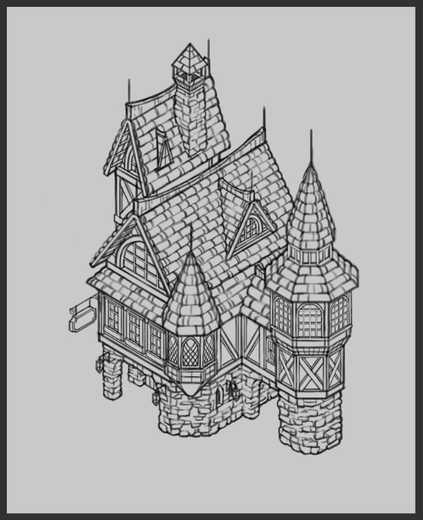
Depict a complex building
Afterwards we know how to what is Isometric cartoon and how to draw a bones house in Isometric view and also how to predict cast shadow in 3D view. Now, I gonna prove you how to draw a building that has more particular and more than complex than the basic house.
Actually process on how I create this building is the aforementioned as earlier, the only difference is I need to put more work on the edifice that I gonna create.
Instead of drawing front view or side view unlike the starting time i, I just leap into the sketch because I know that only front view and side view do not give me enough information to me
in order see how my building gonna looks similar (you lot still can use that method simply information technology'south kinda confusing if at that place are a lot of different shapes in simply one edifice.)
I set my Isometric ruler and Isometric grid in place and starting time sketching on the canvas.
since this a sketch to see the bodily looks of the edifice. I disable Isometric ruler and sketch with my freehand with the just help of the Isometric filigree that helps me guide my line.
Later I've satisfied with the result, I move on to find a clear construction of my building.
Then non only I've created a [New layer] for my structure line and also create a [New Layer Folder] for this
since the structure of my edifice have their own contained shapes and so they're deserved their own layer for that.
I've lowed the [Opacity] of my house to around 25%, prepare for the next process.
The tools that I'yard gonna utilise in this procedure is [Direct depict] > [Direct line].
I've used [Straight line] and with the help of Isometric ruler, created the structure of the master building with the red line.
some function on the edifice that my Isometric ruler tin't perform such every bit a rooftop, I press [Shift] cardinal and so drag the line to where destination that I want the line to exist. With this technique and tool make my workflow much easier.
Afterwards I've Finished with the principal building, I begin to proceed to describe other parts of the edifice using a separate layer.
In this layer, I'm gonna apply a blue color to depict the other part of the building.
After cease, depict the structure on the building., I'll show you lot how to create a circumvolve in Isometric view with the help of the Prune studio paint features. since some part of my building need to use a circle to draw the structure of that part.
The first method I'g about to show yous are [Figure ruler] that create effigy such equally Rectangle, Ellipse, Polygon that your line will follow that figure.
and so I'grand gonna show you how I've used this tool in my workflow.
Starting time, I've selected [Figure ruler] > [Tool holding] > and choose ''Ellispe'' on the figure setting.
After that, I printing [Shift] key to make the scale of my circumvolve equal to each other and depict the [Figure ruler] to the canvass.
When you already take Circle on the canvass, I switch tool to [Object] > use object tool and click on the circle on the canvass > [Tool Property] > change the ''mode'' to [Gratuitous transform]
after you lot change the mode to free transform, yous will allow adjusting similar normally costless transform do. I've clicked on the circle that I've created, and drag every corner of the circle to match to a grid that I've created with Isometric ruler.
Done! now, I have a circle in Isometric view! The advantage of effigy ruler is information technology allows yous to control the lines pressure inside the effigy, which suit to be use in Line art process.
Another method is merely used [Ellipse] and draw on the grid.
This method is very fast and effective, but lack of the interesting since It creates the line without the pressure or size of the line, which this method suit in sketch or structure process.
I continue the depict the rest structure of the building with geometric shapes with purple color.
you lot tin see on the edifice that I've used [Ellipse] to draw the circle the exist main structure of that part.
when I'm washed with the structure part, I've created new layer a draw line art on the building base on the structure folder. start with the main building and pocket-size windows.
when it comes to line art part I can't use [Straight line] to create the line that Isometric ruler can't perform anymore, since I need to create a soft line or requite some pressure into the line.
So I'll switch from using [Directly line] > [Linear ruler].
I've used multiple linear rulers to draw cone of my building, then I describe the line on the ruler control my line force per unit area. like this GIF picture below.
and I'll continue to use this tool with the rest of the role that Isometric ruler can't do.
Subsequently finish with the other office of the edifice. y'all discover the line that still visible backside the new building. and I will use [Layer mask] to hide these lines instead of delete these lines forever.
I've selected the main edifice's layer > click [Create layer mask] and you lot will run across the box announced abreast the main building's layer > make sure you lot selected that white box In order to edit the mask layer.
After making sure you lot've selected the mask layer > I've used [Eraser] to erase those part that I desire to hibernate. y'all tin can notice on the layer'southward thumbnail will alter.
I tend to apply the method a lot when it comes to sketch or line art part. instead of deleting the line yous don't want, you can merely hibernate it away with a layer mask.
Next, I create a new layer and adding some sketch or guideline that will help me add detail on the futurity similar windows. roof tile, stone panel. one with red color and one with purple colour.
one of my favourite role of the whole process is drawing a stone panel! I draw those rock very slowly and make certain that they will have their own independent shapes requite a more realistic look to the rock panel. and I tend to depict to line dark to the side that facing or ground and brand side the facing the top brighter. during this part, I draw the stone with my freehand with the help of isometric and guideline make it much easier.
After I've finished with the stone console I proceed to draw roof tiles on summit with a royal line that I've created guide my line ane by one. I decided to draw roof tile on the main building get-go In order to run into how my rooftop gonna looks like
later on finished with the main building, I continue to draw roof tile on the balance of the building with my freehand.
Later finished draw roof tile I've hidden the roof tile guideline and begin moving to the next part.
Adjacent, I've fatigued a sketch roof windows on the top of the edifice with a pinkish line.
after satisfying with the sketch, I continue to draw the actual line into to roof windows.
about of this part I've used Isometric ruler to drawn the sash of the windows and added some depth to it.
I go along to depict windows on the remainder of the building. simply this fourth dimension I'm gonna use [Symmertrical ruler] to describe my windows on the tower and on the small building.
This Symmetrical ruler volition mirror line from the different side of the ruler, suit for drawing something that similar forepart view windows.
to gear up the ruler on the canvas I printing [Shift] key in order to arrive directly and vertical > and continue the window easily with the help of the Symmetrical ruler.
After that, I copy the window layer with [Ctrl+C] > and paste it [Ctrl+Y] create re-create window on the top of the layer. And so, I've used a shortcut [Ctrl+Shift+T] to [Free transform] the object.
and utilise mouse drag the corner to the correct side, like the GIF motion-picture show below.
I repeated the aforementioned step as the left side of the small building.
and I echo this method to tower's windows likewise.
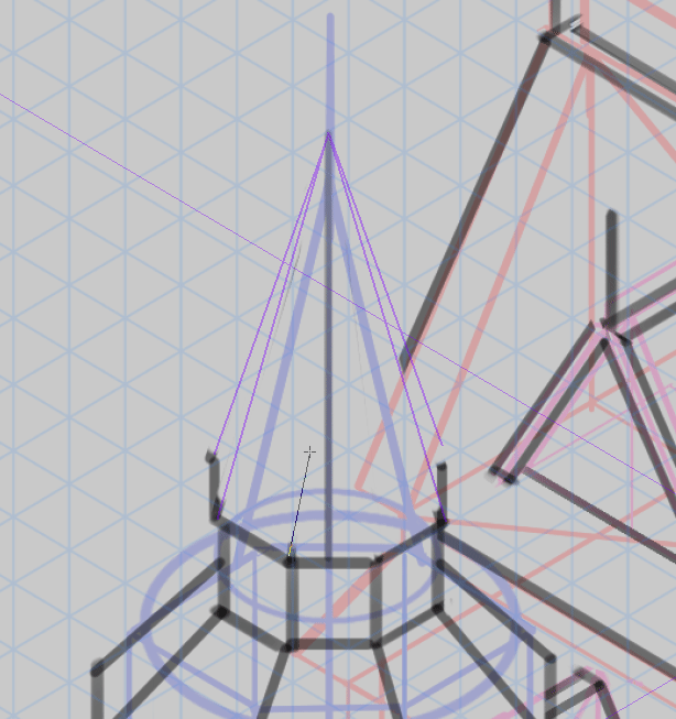
Later finished added windows to the building, I've added a timber frame to the principal building. too added wooden sign and other detail to the building.
I depict the get-go window with help of Isometric ruler on the left side of the airplane.
After giving enough detail to the window, I copy and paste them into the blank space of the building.
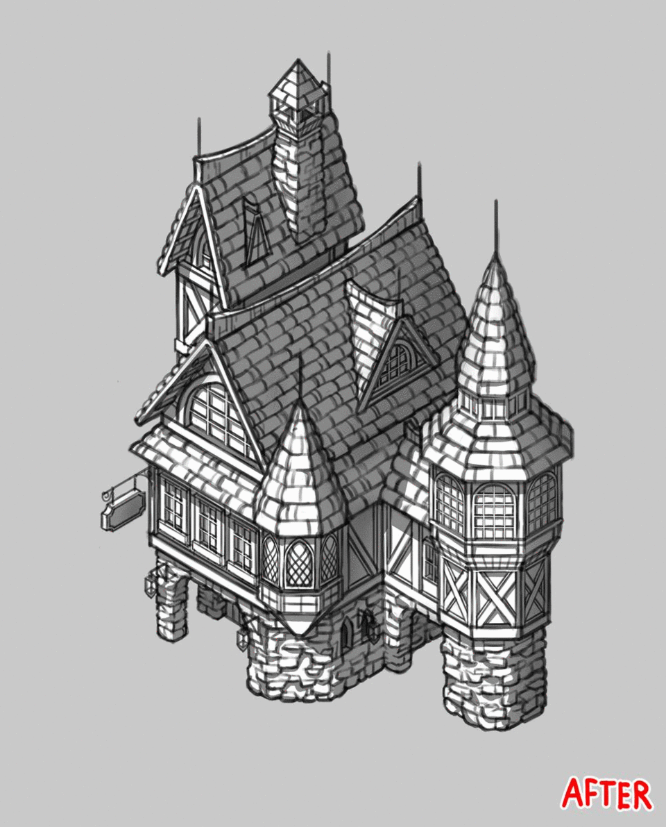
I recall I'thou done with line art function, and then I volition continue to add only a core shadow into the build. since this building is more complicated than the first building so I've decided not to do and then (It'south too hard)
aforementioned like the first building,
1. First, I select the house layer or my line fine art layer
two. I set this layer as a [Reference layer] (After that, yous tin can see the same logo appear in the forepart of the layer)
3. I select [Auto slect] > [Refer to editing layer only] > [Tool property] I bank check '' Multiple referring'' > and cull ''Reference Layer'' (This setting wherever you utilise this tool, everything will base on the reference layer)
4. After the setting has set in place, I've created a [New layer] to be my color layer.
5. I've used [Refer to editing layer but] > click on the outside of the edifice and the pick expanse will announced on the canvass
half dozen. You tin see the mini-menu that appears on the lesser of the selection. I click [Capsize selected area] and you can see the selected area Invert to the space inside the building.
vii. After that, I choose the color that I want to be my base colour. > Then I click [Fill] on the mini menu to make full the area with my chosen colour.
I've created a [New layer] and set the layer setting to [Clip to layer beow] on the meridian of the base of operations color layer, preparing for the next process.
Later that, I've painted the darker color on the edifice. In this adding shadow process, I endeavour to imagine what is light direction gonna come from? and how core shadow gonna looks like.
Most I've painted the major office that I'm very sure those part will embrace in shadow.
Next, I create a [New layer] In order to give detail to my edifice such as stone panel, timber frames.
I've connected to paint those role on the rest of the building. you lot can encounter the different before that, this process gives a significant look at my building.
Even I've hidden the Line art layer, you lot however can tell how the edifice shapes gonna looks like. Thanks to the core shadow.
Finally, I've arrived at the final procedure. After added shadow to the all subconscious part of the building, I will apply [Airbrush] > [Soft] to make some part on my building darker with this airbrush.
I've created a new layer on the top of ''core shadow'' layer and ready this layer setting to [Clip to layer below]
After done will layer setting, I start to pigment on the darker function of the building or the part that hidden very deep from the light with a color that darker than the core shadow color.
Y'all can see the change in this GIF movie beneath.
Writer's word
Thanks so much for reading this tutorial! When I'm working on this tutorial I didn't expect that this tutorial gonna be this long lol, cheers for taking your fourth dimension reading my tutorial!
I promise this tutorial helps you on how an isometric drawing works.
If you take any question please leave the comment below, see you later in the next tutorial!
Users who liked this post
Source: https://tips.clip-studio.com/en-us/articles/2312
Post a Comment for "how to draw a 3d picture easy"